Project Drawings.
A lot of the work that I do is design and build. On other projects we can get basic information but then have to fill in the blanks. Like this for example:

This is a scheme where there were 5 houses and 3 different roof types. But for some reason this roof, Type A, was not detailed, we only had this concept. So it would be very hard to get it priced accurately. To do this I built a basic model of the structure and from that I could then start to build the roof.

Once the 3D model had been created it was possible to see areas that may clash and steels that might be in the wrong position. We could also then work out what rafter lengths to use to best effect. It also meant that we could add dormer windows and veluxs and know they were in the correct position in each room.

Because I am from a carpentry background this really helped me. I have built cut roofs before so have a good idea of what is involved. I also meant that we would have a good idea of what the walls would look like under the truncated hips and how high and where the peirs needed to be to suppor the overhanging sections.
It is important to note that I am not an architect. But because I do have good building knowledge I am able to draw these details and they can then be sent off the the architect to approve and incorporate in their scheme. It cuts out a lot of time.
Drainage and civils.
On some jobs that I work there is a need for drainage but not design for it. In one instance there was a whole road layout to be built, with no design. The road was a rainwater retention system as well which collected all the run off from the houses and slowly released it into the local watercourse. Under the surface of the road was a giant pond liner with a 1000 tons of stones which allowed water to flow through them.
This all had to be done in a certain sequence. Some of the services had to run under the road or cross under the road. But because of the surface water retention scheme under the road, these services had to be deeper than that. There were also pinch points where the road was bounder by properties and we could not run our services through them. So doing this work took carefull planning. On the drawings we produced we showed the excavation in different stages to allow for this. I have shown a combined services drawing below but we also isolated different services so they could be shown on thier own to avoid confusion. We created cross sections through the road to show levels and locations of services relative to each other.
This work was programed as well so we could track it and make it work with the other houses we were building at the same time.


Drawings and designs done for other companies.
If you look on the Projects page you will also see specific drawings that we have done for projects where we have been involved in the construction which have been design and build.
We have been working now for some time with Roman Pools doing drawings for them for their pool M&E.
Below are some of the drawings that we have recently done for them on one project in Regents Park, London.
Below is the GA that we were supplied with. We have made their original drawing into one group and layer and made it all dark grey so that the items we overlay stand out more. In this drawing we have added all of the pool fittings, pipe work and plant along with some setting out dimensions.

Below is a GA that we were provided with and adapted as above and we have added the pool ducting, plant room and other details overlaid on it.

Below is construction details for the stairs down to the pool that had to be constructed. These drawings were done from scratch in the case of the stairs and also most of the plant was "built" from scratch if the item was not available in DWG.

Here is an elevation and schematic of the pool plant room equipment.


On this project we also had to go to site on occasion and attend design meetings with the principle contractor and their designers.
On some other projects we have had to do all of the work from scratch such as this one in Kent. This was for a pool that the client wanted to put into a planning application. This was a challenging project as it was in green belt land in a site of outstanding natural beauty and the existing property was Grade 2 listed.
This drawing was sent in for planning along with 1:500 OS plans. The drawing underneath this is the existing property with references to pictures that we took on site and the direction that they were taken in. This was put in a word document along with a desciption of the house and materails that it was constructed with.


Joinery items.
I appreciate the resolution of these images is not that good so if you wish to see the original drawings then please get in touch and we will arrange to send them over to you.
This was a front door that we made for a client. Below is the final client approved design and then below that is the finished product.


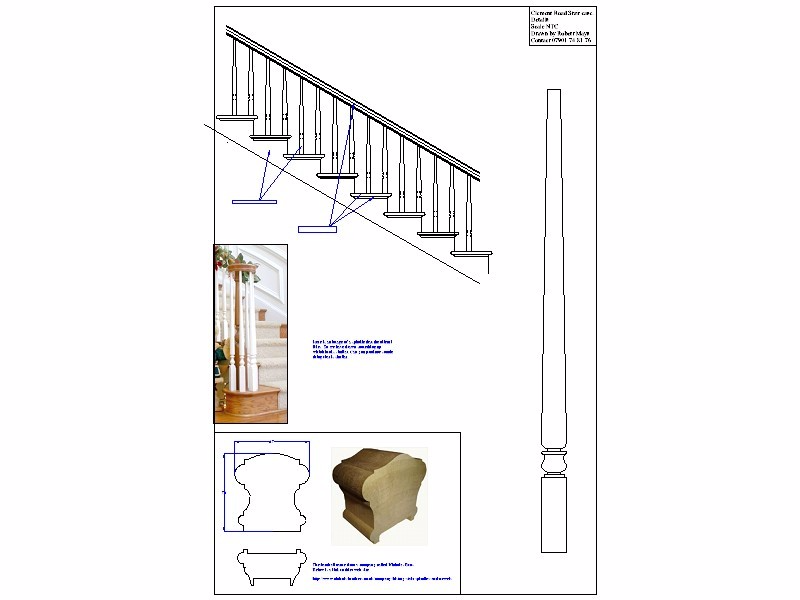
Below are some drawings for another house where we were asked to do the doors and the staircase and wood paneling in the hall way.